Introduction
Making astronomical mosaics is a difficult task. There can be intensity and gradient differences that make the seams visible. Even when the intensities are matched you may find there are noise profile differences. Luckily PixInsight has many tools that help with creating seamless mosaics.
My preference is do the mosaics in linear form that way a any non-linear stretching is always consistent across the panels. This causes some complications like pinching artifacts around bright stars on the seams, but I generally find it preferable to dealing with data that has different stretches applied.
Thanks to Anis for allowing me to use his Cygnus Region data as the basis for this tutorial.
The Mosaic Processing Flow
The general process goes something like this:
- Crop out low signal areas
- Even out background gradients
- Organize Panels
- Estimate area covered
- Create Catalog Star image
- Register panels to Catalog Star image
- Adjust the intensity of each panel so they match up
- Crop the panels down if necessary
- GradientMergeMosaic test
- Crop out stars causing pinching
- Repeat the last to steps until you have a clean results
Cropping out Low Signal Areas
The first thing we need to do is make sure to crop out any empty regions and low signal areas. Bring up the DyanimcCrop process and click and drag a box in one of the panels covering most of the image. Now zoom at a scale of 4:1 or something like that and check out the corners (see Figure 1).
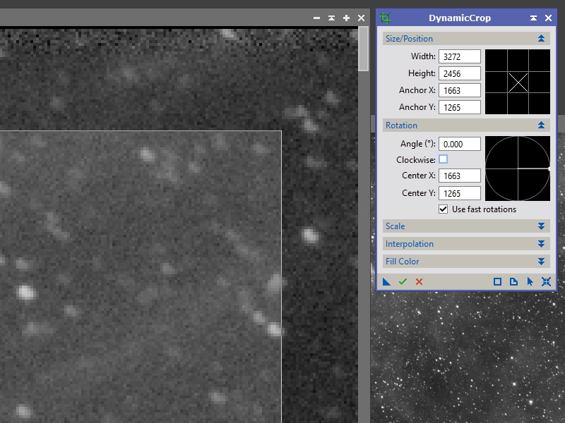
Figure 1: initial crop box
Move your cursor to the corner of the box you’ve drawn and you can click and drag it to a new position. You can also rotate the box, adjust one edge at a time, etc. In this image the first row of pixels is all black and several pixels below that have a higher noise profile compared to the remainder of the image so we are going to adjust the crop box to just below that (see Figure 2).
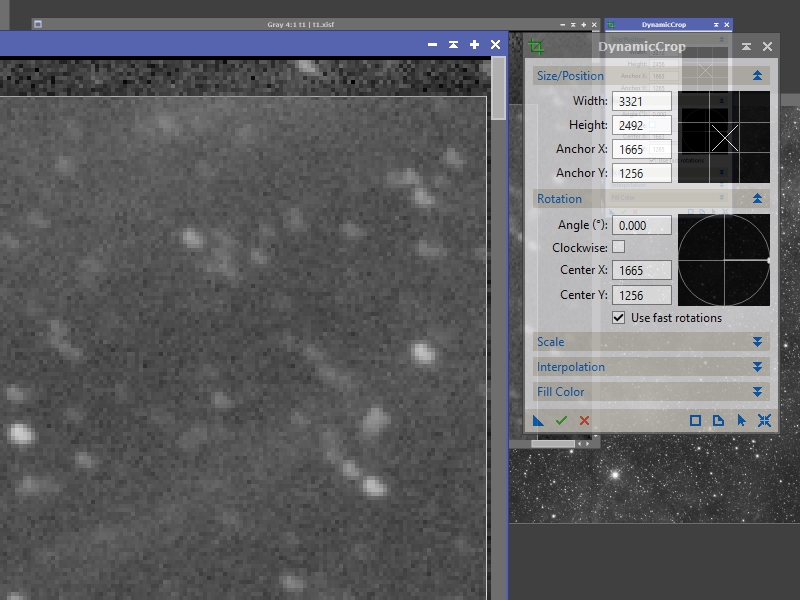
Figure 2: adjusted crop box
Once you are satisfied that you are selecting the best parts of the image click the check-mark icon on the DynamicCrop process to apply it. This procedure needs to be done on every mosaic panel to make sure that the seams are as clean as possible.
Evening out Background Gradients
If you want the best results you will need to make sure that the backgrounds of your images are as even as possible. This can be difficult if you have a lot of nebulosity in your images. I’ve described two methods for doing this in previous tutorials. You can use a synthetic flat or DynamicBackgroundExtraction (described fairly early in the M42 tutorial). There’s one other method I haven’t talked about, AutomaticBackgroundExtraction (ABE). In general when I use this tool, I use the default setting except that I enable the correction method ‘Subtraction’. I’ll run a pass to check what the background model looks like. If it looks ok, then I’ll enable the ‘Discard background model’ and ‘Replace target image’ options so it updates the current image (see Figure 2a).
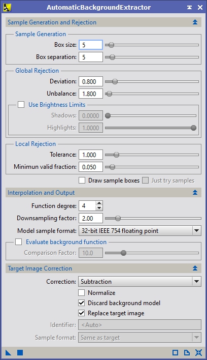
Figure 2a: AutomaticBackgroundExtraction
Whichever method you choose, repeat the process on each panel so that the backgrounds are as even as possible. This will help the GradientMergeMosaic tool later on and give you a smoother looking result.
Organizing Panels
If you have a lot of panels it really helps to organize them spatially to get an idea of how they are laid out and to gather some information about the field of view they cover. I generally rename the panels t00, t01, etc. to make it easier to keep track of which panel goes where. Figure 3 shows me moving one image over another to get an idea of how they line up. In order to see the frame behind the one you are moving, the translucent options need to be enabled in the Global Preferences under Special GUI Effects.
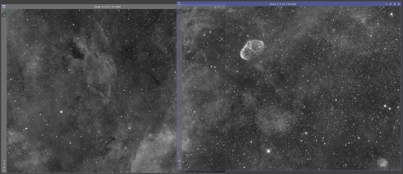
Figure 3: organizing panels
Estimating the Area Covered
If you just have a couple panels you can register them to each other, but for multi-panel mosaics I prefer to use a synthetic star field and register each of the panels to that. In order to generate that star field we need to know approximately where the center of the field, what the image scale is and how much sky is covered.
I know that Anis used a Takahashi Epsilon 130d and a KAF-8300 based sensor. This results in an image scale of around 2.59 arc-seconds per pixel. There are many calculators available to do estimate this, but in this case, I’m going to use PixInsights plate solving and image annotation script to get a more accurate measurement of the image center and image scale. Go to SCRIPTS->Image Analysis->ImageSolver and select the search option. This will pop up a new form which where you can search for an object. Either put in the primary subject of your image or find something that is close and enter it. Hit OK and this will populate the coordinate information in the original form. You can also use a planetarium program to estimate a central location. Since NGC6888 is off-center in Anis’ image I used the second method and entered an approximate center manually. I also populated the focal length and pixel size of Anis’ scope and camera (you can also just put in the image scale directly if you know it). Figure 4 shows the settings I used. Clicking OK will run the script and if everything goes well it will update the image with information about how it maps to the sky.
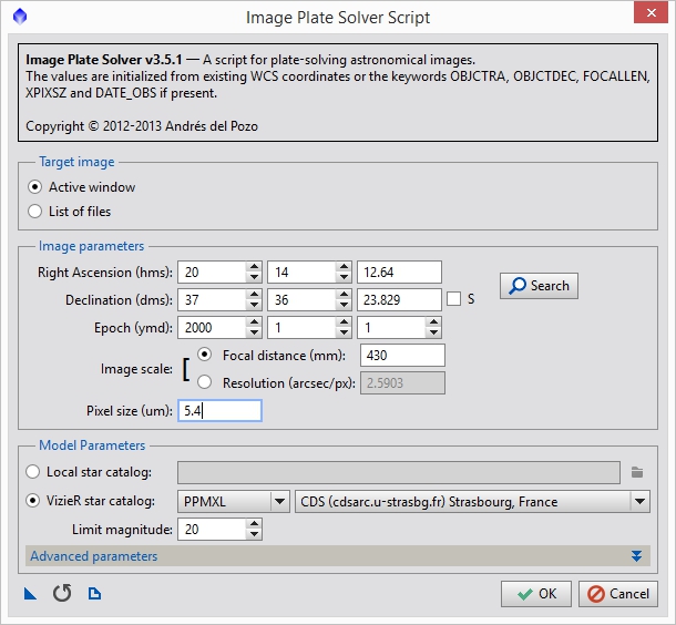
Figure 4: Plate solving script
After the plate solving script completes you should see something like Figure 5 in the console. This shows information about the image scale (Resolution), rotation, true focal length, image center, field of view, etc. This information is also populated in the FITs header of the image so other scripts can reference it.
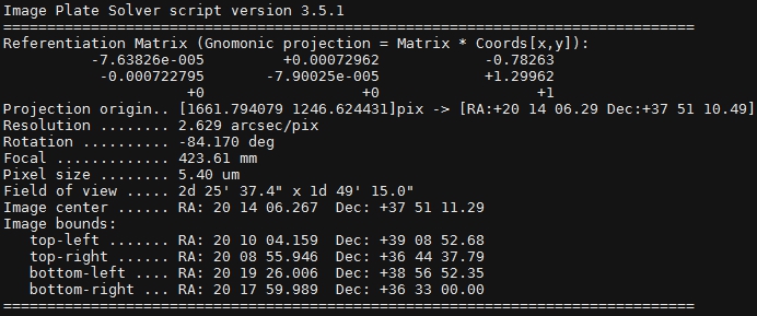
Figure 5: Plate solving results
Now that the image has been updated with its plate information we can run the Image Annotation script to estimate the center of the field of view of the entire mosaic. Go to SCRIPTS->Render->ImageAnnotation and you should see something like Figure 6.
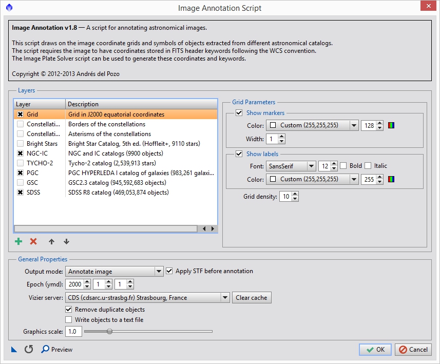
Figure 6: Image annotation script
You can select what layers you want, but primarily what we want is the ‘Grid’ option. You should also increase the ‘Grid density’ option so that we can use the grid lines as a reference for the frame center. This will vary based on your image size. For Anis’ image I used a grid density of 20. Since the data is linear, make sure the ‘Apply STF before annotation’ option is on. This will generate a new image populated with a grid showing the RA and DEC values. Using the same technique as we did above dragging the image over the other panels we can estimate where the center of the total field of view is (see Figure 7).

Figure 7: Overlaying the image with the reference grid
Based on the above I estimated that the center of the field for these two images was: 20:14:35, 38°50’48” N. From the plate solving we also know that the field is rotated -84.17 degrees and the image scale is 2.629″/px.
Create Synthetic Star Field
One of the reasons I use this method is because it gives you control over the field curvature present in all optical systems and allows you to setup a map everything to a particular projection method. The CatalogStarGenerator script used Gnomonic by default, but other methods are possible. For this example I will use the Gnomonic projection method.
Go to SCRIPTS->Render->CatalogStarGenerator which will bring up the script we will use to generate our star field. Each of the panels in this data set are about 3320 pixels across and 2500 pixels high. We have a little vertical offset and probably something like a 15% horizontal overlap. This means, in terms of pixels, the field covers approximately 6142 (2*3320 – 0.15*3320 = 6142) horizontal pixels and 2700 vertical pixels. I usually pad this out a bit to be sure that I am covering the field adequately (I decided on 6500×3000 for this data). Figure 8 shows the settings I used for the Catalog Star Generator script. You can see where I populated the other information we gathered. Figure 9 shows the synthetic star field on top of the the other two images so you can see approximately how they line up.
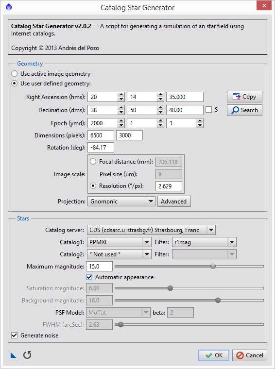
Figure 8: Catalog star generator
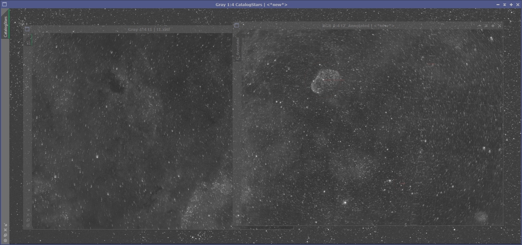
Figure 9: Synthetic star field overlapping the other panels
Registering the Panels
Now that we have a single reference image we can register each of the panels to it. Bring up the StarAlignement process. For the reference image, switch it to ‘View’ and then select the CatalogStars image. Because the projection model may not match the curvature of your optical system I suggest turning on 2-D Surface Splines and Distortion correction. This will help make the mosaic more seamless. Leave the ‘Working mode’ set to ‘Register/Match Images’, just as if you were doing normal star alignment. You may need to increase the RANSAC tolerance to deal with the differing curvatures. Also, to make the registration more robust and a bit faster it helps to turn on the ‘Restrict to previews’ option and create a preview that covers a bit more than the area of the panel you will be registering. Do not use the ‘Frame adaptation’ option, we will deal with intensity matching separately. The rest of the settings should be similar to what you normally use. For example, I am going to register the left panel first, so I created a preview in the CatalogStars image that covered top to bottom, all the way from the left to a little past the middle (see Figure 10).
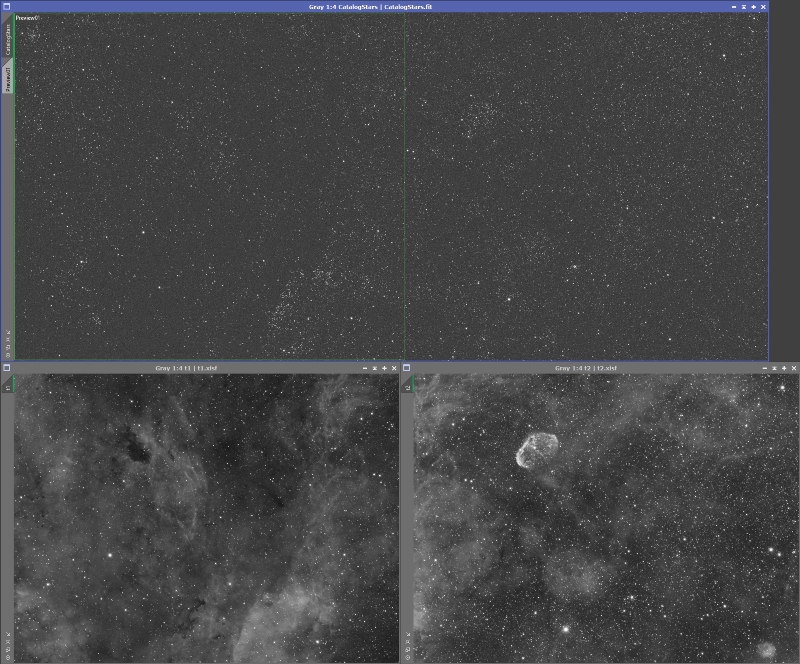
Figure 10: Preview for registering the left panel
Figure 11 shows the full set of StarAlignment settings I used for Anis’ data. Drag the ‘New Instance’ icon (the small triangle on the lower left) from the StarAlignment process to the left image panel (which I called ‘t1’). You should get a new registered image that looks something like Figure 12. Repeat the process for all panels, adjusting the preview appropriately.
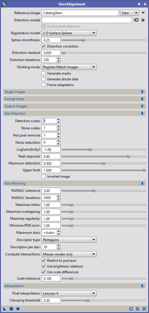
Figure 11: StarAlignment Settings
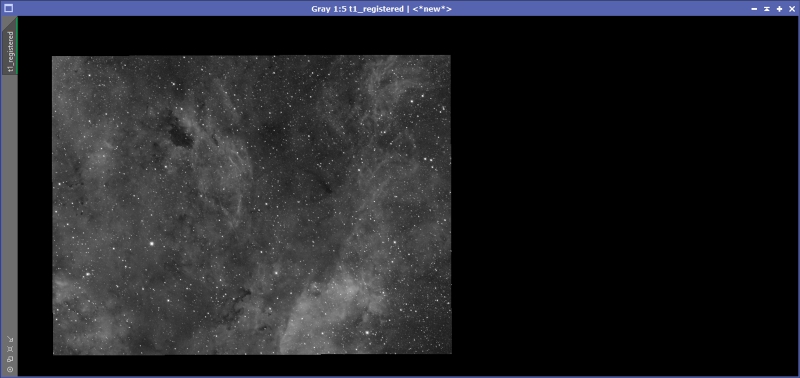
Figure 12: Left panel registered
Intensity Matching
The next thing we need to do is match the intensities of the two images so that GradientMergeMosaic (GMM) can do a better job at merging the panels. Normally I would use the LinearFit process for this, but it has one big issue. When it adjusts the image it can raise the background level as part of the fit. This does not play well with GMM which requires the parts of the image that do not contain data to be entirely black. In order to get around this I wrote my own linear fit script which you can download here (click the link, then click the download button – do not copy and paste the text). To install it, copy it into your PixInsight/src/scripts folder then go to SCRIPTS->’Feature Scripts…’ and click ‘Add’ button. It will ask you for the directory, point it to your PixInsight/src/scripts folder and hit OK. It should find the script and make it available in the SCRIPT menu. It will show up under Utilities->’dnaLinearFit 0.1′.
Before we launch it, let’s make sure the images have the same ScreenTransferFunction (STF) stretch applied. By the way, all the images in this tutorial have had an STF auto stretch applied so the data is visible since the data is still linear. Once you have STF process up, apply a stretch to the right panel, then drag the ‘New instance’ icon from the STF window to the left panel. This will apply the same STF stretch to the left panel. In my case the left panel is much brighter so it shows up as almost white. This isn’t really a problem as STF does not modify the data, it just alters how it is displayed.
Now we are going to adjust the left panel so that it has the same intensity profile as the right panel where the images overlap. Bring up dnaLinearFit and select the right panel as the ‘Reference View’ and the left panel as the ‘Target View’ (see Figure 13) and hit OK. You should see the left panel show up clearly now.
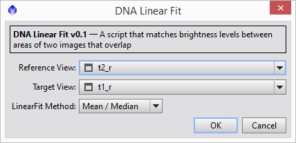
Figure 13: Linear Fit
Cropping the images down
Now that we have intensity matched registered panels, let’s make a first pass attempt at a mosaic and use it to crop the data before feeding it to GMM. Bring up PixelMath and we are going to a maximum function between all the panels (see Figure 14). Hit the ‘Apply’ button it will generate a new image. With Anis’ narrowband data this almost look perfect just as it is, but there are some minor seams, so we’ll continue on (see Figure 15).
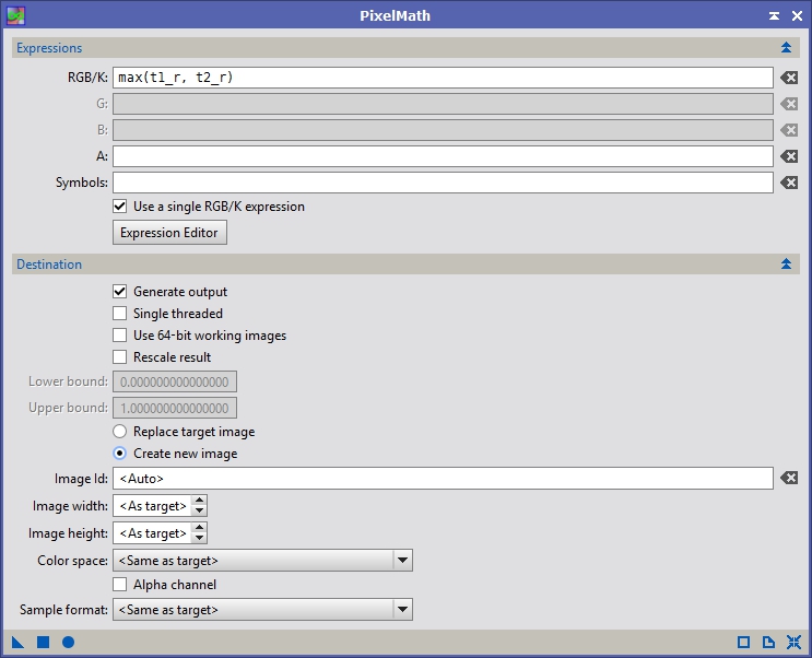
Figure 14: Maximum of panels

Figure 15: Maximum of individual panels
Now bring up the DynamicCrop process and select the the portion of images you want to be in your final image. GMM can have problems with corners and black around the image so I general crop into an area where data exists everywhere. You don’t need to crop that image, instead drag the ‘New Instance’ icon from DynamicCrop to the PI desktop to save that crop. That crop can now be applied to all the panels by dragging the desktop icon to each image. After applying the crop to all panels you should have something that looks like this Figure 16.
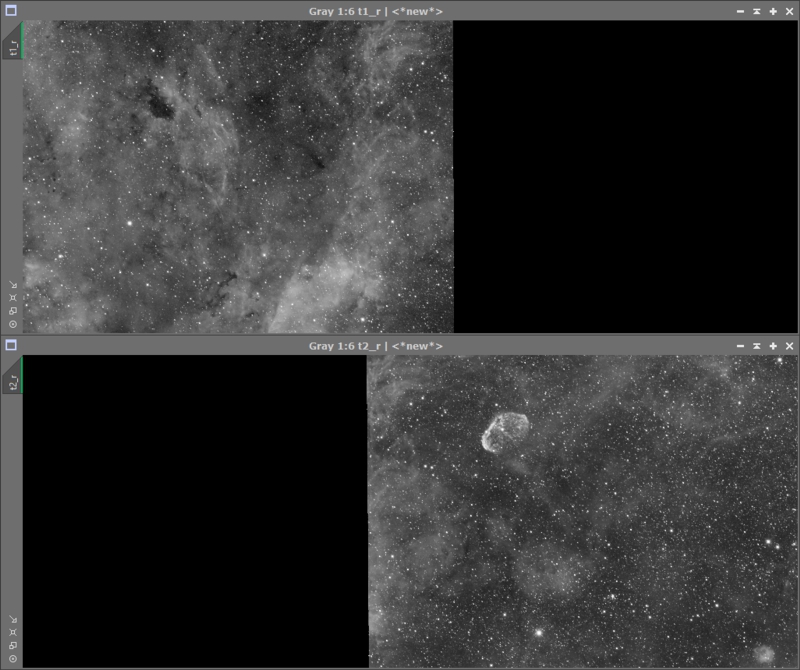
Figure 16: All panels cropped down
Save the panels to disk now as GMM cannot reference views in PI.
Gradient Merge Mosaic
Bring up the GradientMergeMosaic process and add the files that we’ve registered, adjusted and flattened. Generally I use all of the default settings so you can just click the ‘Apply Global’ button (see Figure 17). It might take a little while but eventually you will get two images, one will be the completed mosaic and the other will be the mask, showing how it merged the panels.
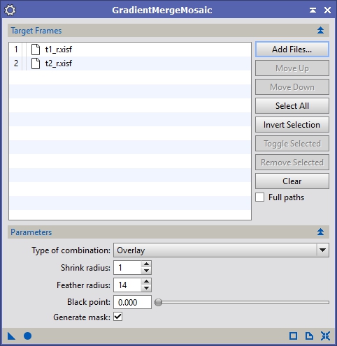
Figure 17: Gradient Merge Mosaic
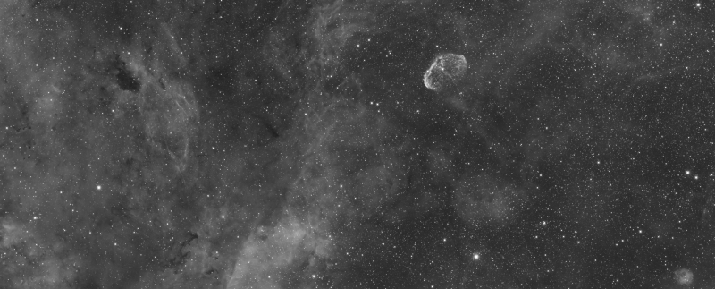
Figure 18: The merged mosaic
Cropping Out ‘Pinched’ Stars
Anis’ data came out perfect, which is a bit disappointing, because I found no issues around any of the brighter stars. However, for completeness sake, I’m going to pretend this happened and show you how I deal with them. Bring up PixelMath and reset it to defaults (the X looking icon in the lower right), then put in this expression: iif(x()>2659 && x()<2671 && y()>2304 && y()<2320, 0, $T). The x & y coordinates in there are the values around a bright star I found on the edge of one of the panels. They mark the bounds of the star with the x ranging from 2659 to 2671 and the y ranging from 2304 to 2320. I just move my cursor around the offending star and watch the xy values listed on the bottom bar of the PI window to find the coordinates. Figure 19 shows a zoomed in image of the right panel around the star before and after applying pixel math to it.

Figure 19: Star Removed
After removing any stars near the edge of a panel that is showing pinching in the final mosaic, save the image again and then re-run GMM. Keep doing this until you don’t see any artifacts around stars. The last pass with no artifacts will be your final mosaic.
I hope you find this tutorial useful.
I’d like to personally thank you for your “DNALinearFit” script, which is incredibly useful for mosaic construction. I had some trouble with a recent mosaic of mine, due to having captured a panel near a full Moon. Your script really did the trick of sorting that out, so thank you! 🙂
Also, this tutorial of yours is excellent. I particularly like your technique of “cutting out” problematic stars with PixelMath.
I’m glad you found it useful Kayron 🙂
Regards,
David
Thank you David for this great tutorial.
I’m working on an 8 panel HaRGB mosaic. It’s the first time I’m doing this and I’m wondering if it’s better to make 8 HaRGB images then make a mosaic, or to make a mosaic for each channel then combine the 4 mosaics in HaRGB ?
Thanks again for you tutorial and for your script!
Kind regards,
Nicolas
Hi Nicolas,
I have found it better to do each channel as a mosaic, so putting all the Ha together as one image, then all the R, etc. If you do it the other way you have to make sure that all the intensities match up between all channels and all panels. If you do it as a mosaic for each filter then you can put it together as a regular HaRGB afterwords.
Regards,
David
I have been trying to make a 4pane mosaic in Cygnus….however, no matter what I try…Frame adaptation, linear fit, DNAlinear fit the background of one frame appears completely clipped in the shadows.
They look fine when registered…but somehow when GMM takes over any differences are so much exagerated…especially when I remove the stars….then it is obvious.
Any ideas?
Hi Dimitris,
Sorry, it’s taken me a while to respond, but I’ve changed email systems and wasn’t getting email from my website. I’ve just updated my dnaLinearFit script which you can download from here. Let me know if that helps. If it doesn’t maybe if you upload some of your data I can take a look at it and see if I can figure out what’s going on.
Regards,
David
David, I like the script but I’m having problems getting all my panels in a mosaic to have similar background levels. Is there any chance because a couple of my panels are devoid of background (all nebula), it’s messing up the script?
Thanks, Goofi
Hey Goofi,
As far as the script is concerned it doesn’t matter if one image covers the entire field with real data and another doesn’t. All it does is look for non-zero pixels that the two images have in common and determines a linear fit between them using only that information. If the ‘Mean / Median’ mode is not giving you the best result try the ‘Least Squares’ algorithm instead and let me know if that does any better. I’m not sure what GradientMergeMosaic is going to do with a mosaic where one of the panels covers the entire field though.
And just to be clear, when you are using the script are you doing it between panels that are already registered to the mosaic?
Regards,
David
Thanks for the reply, David. Yes, I’m pretty much following your tutorial for mosaics and creating a synthetic star field as best I can (it’s a 9-panel mosaic, and I think the distortions are causing some problems registering all of them). Once I have the panels registered, I’m trying to use the script to normalize my backgrounds.
G
Once you get past a 4×4 mosaic, they definitely get very difficult. This would be my approach: once I had all the panels registered, I’d start with the center image and work my way out. Lets say you name the panels p00 through p22, so that the upper left panel is p00, the upper right is p20, the middle is p11, the lower right is p22, etc. I would do a dnaLinearFit, with p11 as the reference, against the target panels p01, p10, p21 & p12. Then I would make a quick mosaic using PixelMath. Use this expression with p11 as the target (you’ll need to undo the changes, so save the file before you do this just in case): iif(p11>0 && p01>0, (p11+p01)/2, iif(p11>0, p11, p01))
That will merge p11 and p01 into p11. Run the same expression another 3 times changing p01 to p10, p21 & p12 respectively all with p11 as the target. You should end up with p11 looking something like a plus sign.
Now use dnaLinearFit again with p11 as the reference against p00, p20, p02 & p22. Back out the changes to p11 and save all your files (you can overwrite them if you want, but I would save then with a postscript of _lf or put them in a LinearFit directory). Try GMM with those files and see how it works. Let me know how it goes.
Regards,
David
Hello David, I want to thank you very much for your great tutorial.
I was working on a 4×4 mosaic but I couldn’t get through the process. Your tutorial made me succeed in the process 😉
Again, thank you very much.
Regards,
Alexandre
Glad it helped Alexandre!
Regards,
David
Hi David,
Thanks for the tutorial, I’d never tried GMM before and it’s worked wonderfully – thanks!
http://www.astrobin.com/216596/
Simon
I’m glad the tutorial helped Simon. The mosaic looks great!
Regards,
David
Hi David,
Great tutorial! I’m working on a 4×4 and was having star pinching problems. I didn’t like the idea of having to use PixelMath for cropping unwanted features (should be an easier way), but finally dove in and found success. Once I got going, I did one more step on cropping — that is I squared the overlapping edges first and then came back and had to nip out only two stars.
Also the user discussion here gave me direction on doing the mosaic for each filter first. Good stuff.
Thanks,
Mark
I’m glad you found the tutorial useful Mark. Do you mean that you made the seems parallel to each other? If so, I’ll have to experiment with that and add it into the arsenal of what to do when things go wrong with your mosaic.
Regards,
David
Thanks David.
Yes exactly, seams parallel. In my case, and this mosaic, it seemed to make the joining manageable.
Mark
That’s interesting. I’m curious to find out why that is the case. I’ll have to dig into this more and then I can update the tutorial with that info. Thanks Mark.
Regards,
David
Hi, I am trying to compose a wide field mosaic of the cassiopea-perseo-andromeda-tauro region taken with a 50mm lens, and find your tutorial very useful. However, I am stuck at step ‘Registering the panels’ since the staralignment of my already ‘solved’ image and the reference syntetic starfield fails. Also the process of trying different parameters in the form is tedious because each try the staralignment process go up to 32000 stars! Also, the cancel button does not work. So I would be very grateful if you could: 1) tell me how to limit the number of stars down to 12000 aprox, 2) give me a hint of what can be the best parameters choice for my case, 3) tell me an alternative to staralignment just in case…
Thank you in advance!
Hi Angel,
One way to limit the number of stars detected when registering your data is to increase the ‘Star Detection’, ‘Log(sensitivity)’ setting. The default is -1 but if you push that up to 0 or even +1 you should see the number of stars used for registration drop dramatically. Without having your data on hand, I can’t really tell you exactly what setting to use but you might start at +1 see what you get and then go up or down from there.
In your case you might go for option 3, which is to use the MosaicByCoordinates which is available under Script->Utilities. The requires that each panel (not individual sub frames) be plate solved using the ImageSolver script under Script->Image Analysis. As long as that information is populated in the FITs header of the image, MosaicByCoordinates does a great job of stitching very wide field mosaics together and gives you the option of different projection methods.
Regards,
David
Thank you David,
pushing up the sensitivity level worked! I am grateful for your comments and thank you for the excellent tool DNALinearFit.
Best regards,
Angel.
No problem Angel. Glad it helped!
Regards,
David
Hi Dave,
I am just getting into this Mosaic stuff and your article has been a HUGE help, along with your script !! Just one question, do you recommend or use any other processing tools (other than ABD or DBE) before running the rest of your routine, i.e. noise reduction, morph transformation, etc etc .
Happy Holidays !!
Hi Dennis,
If there is a noticeable discrepancy between two panels I will sometimes use noise reduction on one or more of them to balance things out a bit. This is very difficult to do because you are trying to match the noise profile of the other panels. It generally takes a lot of trial and error to get it right. I typically use TGVDenoise and MultiscaleMedianTransform together with various masks to do noise reduction. My M42 tutorial shows how I typically handle noise reduction.
Regards,
David
Hi David,
I watched your presentation on the TAIC and found this tutorial afterwards. It’s brilliant, thank you so much ! I’ve spent 2/3 long days trying to get a 4 pane Ha mosaic together, trying everything I knew, all sorts of DBE attempts and variations, and no matter what I did, there came a point when the panes started to show up somewhere.
But I’m really thrilled I’ve learned a lot new from following these steps, and I’ve done my first successful pixel maths along the way as well! The result was so seamless, I’m amazed. Data collected over 2 years has been put to brilliant use at last. I literally can’t thank you enough, it has completely transformed GMM for me…
Now for the RGB data – fingers crossed it works so well !
Regards,
Kit
Thanks Kit! I’m glad this helped work through the problems you were having with your mosaic. It’s a nice surprise when you go back to older data you thought was bad in some way and are able to get something out of it. Let me know if you have any other questions and I’ll be glad to help.
Regards,
David
Thanks David ! It’s only old data as it’s taken me so long to get the data together as we had an awful spell of weather last year, and I foolishly started on an 8 pane mosaic before finishing this one off ! And it takes a while to amass 30 min Ha subs 🙂
I didn’t have quite as much joy when assembling the full HaRGB image as the levels for one half of one (or more) of the colour channels don’t seem to balance. I haven’t really experimented so will start to do so. But can I check one detail, please?
I have 4 panes – top left is 3, top right is 1, bottom left 4 and bottom right 2. In the final image the colour is different on the left hand side (ie 3 & 4) to the right (1 & 2).
I put each channel together separately. When I got to the script stage I used 1 as the reference and 2 as the target. Then I used 2 as the reference and 3 as the target, and so on. Is this the wrong thing to do – should I be using 1 as the reference for all 4 panes?
Thanks so much for your offer of help, much appreciated and again, wonderful script I’m so much further forward than I was !
Regards,
Kit
Hi Kit,
It is better to use only one frame as the reference if possible. This isn’t always the case though. For example, you may not be able to use panel 1 as the reference for panel 4. If that’s the case typically what I do is construct mini mosaics, like taking panel 1 and two combining them and then using that image as the reference for the other two panels.
In general I construct mosaics in monochrome form and then treat them as one large LRGB, SHO, etc. image. I’ve found it easier to deal with the color gradients this way. Although if you are doing many panel LRGB or RGB mosaics in a light polluted area this becomes increasingly difficult. I’ve been working on another script to help with this but it is still buggy and I have not had time to get it working 100% yet.
Regards,
David
Thanks for the quick response David, that makes perfect sense. The new script sounds great I look forward to using that !
Regards
Kit
Hi David
I have been using Kayron’s video’s for some time and using his video on mosaic’s he mentioned your program for matching the intensity of each image. I was having trouble on my first attempt at merging 2 images and finding that one came out very grainy and looked very noisy. However, I downloaded your script for intensity matching, applied it and rather magically (always the way with this Pixinsight stuff!), it came out with both halves of the image joined as if they were one.
Can’t thank you enough, magical stuff.
Best wishes
Alec
Hi Alec,
That’s fantastic! I’m glad it worked well for you.
Regards,
David Ault
Hi David,
I have some processing questions that is off this topic.
If you could contact me by email I would to talk about it.
Max
Dave,
I’ve searched your website and blog for over an hour.
How do I join, and how can I get your blog sent to me?
Thanks
Bruce Lathrop
Los Angeles Astronomy Society
Hi Bruce,
Unfortunately, my website isn’t really setup like that. I’m not much of a web developer so I use the site more as a repository my tutorials than anything else. At some point I will update it to support some of these types of features, but not right at the moment.
Regards,
David
Hi David,
First of I want to thank you so much for this tutorial! I’m working on a 32-panel mosaic of the Milky Way’s core for a school project, and it has been quite the challenge! I’ve been using your DNALinearFit script, and it works absolutely great for a small number of images (for instance, when doing the first row of the mosaic), but when I keep going, a few panels do not want to cooperate and come up with a very high about of clipped pixels (in the thousands) and the frame will usually be very purple/blue washed! Any suggestions on how to avoid this?
Thanks!
Hi Jordan,
That sounds like a very interesting project! My first suggestion is to try some of the other fitting modes like ‘least squares’ or ‘scalar’. With some data sets those do a better job at determining the fit. It sounds like the green channel is not being fit correctly, so another option is to see what scaling values are being reported by the script for the blue and red channels and use those scaling values instead (this can be done with PixelMath). One of the things to look for that can throw any of the linear fit processes off is non-zero values outside of the active portion of the image. Check for that as well. If you can point me to two of the panels that are not fitting correctly, I can also take a look and see what might be done and may be able to tweak the script to work better.
Regards,
David
David,
I think the scalar mode is the one!(knock on wood!) I’ll send over the results when it is finished!! (now just have to make sure all the frames are fitted in an hour and twenty min to get it printed…)
Thanks a ton, Jordan
I clicked on the “here” link to get your DNA Linear Fit script, and right clicked on the Google Drive page and saved it in PI’s scripts folder. Then I went in to PI and clicked on SCRIPT > Feature Scripts and then clicked on Add and selected the Script folder. Then PI gives me the message that 0 new scripts were found and then it begins to search the script folder forever until I click cancel.
Am I not following the install instructions correctly? Or do you know why I’m having this issue?
Thanks for sharing your skills with all of us.
Hi Jamee,
Your description sounds like the correct procedure. Have you installed the dnaLinearFit script before? If so, it won’t find a new script but it will cache any changes. PI searching forever seems to be a bug. I just tried it and got the same thing. You may post that on the PI forum or see if someone else already has.
Regards,
David
Hi David,
thought I had a pretty good handle on the process until I took on a 3 (h) x 5(v) mosaic. This is a 15 panel mosaic of M42 with my 12″LX200 reduced to a 2167 F.L. There is a substantial brightness variation from the center of the mosaic to the perimeter.
Everything works well until I get to the Intensity Matching section. I arbitrarily picked a corner panel (#1) and applied that panel’s STF stretch to all the other 14. I again selected the #1 panel as the reference for the dnaLinearFit to all the rest. This results in about half of the panels going black, and staying black. I also tried working from the middle and referencing an inner panel to its outer adjacent panel. This results in the innermost going white (or close to it) and staying that way.
I’ve done the Pixel Math operation to establish the complete mosaic crop, but as mentioned, there are either missing panels or alternatively, mostly white panels.
Thanks for your help,
Mark
Hi Mark,
Unfortunately all intensity matching tools are highly effected by issues like strong gradients. Have you done any ABE/DBE to try to correct the individual panels before fitting them? You might also try some of the other fitting algorithms in dnaLinearFit like least squares and scalar. In some cases they do a better job of determining the fit. Least squares tends to be more robust. If that fails draw a previous on one panel so that it will overlap with another panel’s data. Once you think you have it right duplicated it on the panel that you are trying to fit to this one. Clone those two previews to separate images and use the LinearFit process between the cloned preview from the reference panel and the cloned preview from the other. It will write out some information in the console like y = * x + . This is the calculated linear fit function. You can apply this to the panel you want to fit with PixelMath like this: iif($T>0, *$T + , 0)
The in-line if function just makes sure that black values stay black which is needed by GMM. This unfortunately gets painful trying to do this between 15 panels.
I don’t know if this will fully solve your problem, so let me know what happens and we can debug further.
Regards,
David
Hi David and thanks for the response.
Your suggestions have been helpful, but I’m not quite there and may set this project aside for the time being. One (of many) thing(s) I had not considered is how bright the center of the M42 nebula is versus the outer perimeter.
A question:
Does the STF stretch in Intensity Matching have any affect on the dnaLinearFit operation? Or is it just for the benefit of the viewer?
Thanks,
Mark
Hi Mark,
I understand. Once you get past 2 panel mosaics they can get very difficult. The STF is just to make things visible. By applying the same STF between frames it can also become obvious if there are strong differenced before or after the fit.
Regards,
David
Hi David,
Thanks for publishing this. I found it very helpful as I worked through my first mosaic. Instead of using pixelmath to cut out border stars, I just used the clone stamp. I found this to be a bit faster and at least in my first mosaic it worked very well.
Thanks,
Richard
Hi Richard,
I’m glad the mosaics tutorial has been helpful. I originally played around with using clone stamp and sometimes I got it to work well, but not always. The problem I had was that clone stamp doesn’t have a hard edge and since GMM relies on the value of 0.0 to flag something as ‘no data’ parts of the clone stamp area will be darker but still be considered as data. The lead to some dark rings around stars where I did the clone stamp-ing (different from the pinching effect). This is why I moved to the PixelMath operation. Setting softness to 0 will help but does not entirely remove the problem. If you are not seeing the effects then certainly clone stamp is a much faster way of doing this, but if you run into dark rings you might do the pixel math operation for at least those offending stars.
Regards,
David
Hi David,
Your script has once again proved a ‘go to’ to help me put together a mosaic. I wonder if I could pick your brains though? I’ve just finished assembling an 8 pane HaRGB image – widefield horsehead to M42. I’ve assembled an 8 pane Ha mosaic and the same for the R, G and B channels.
However, when I assemble the colour image, it seems the two extreme right hand panes in the green channel only are a tiny bit misaligned. I didn’t use 2D surface splines to register the panels but the whole of the rest of the image is fine ! I’ve tried re-registering the two offending green panes with the surface splines model but still no joy.
I’m a bit unsure as to what to try next. I don’t really want to have to re-register all 8 panes using surface splines in all of the channels, as it’s taken ages to get to this point !
Equally I’m baffled as to why the whole of the red and blue channel mosaics all seem to perfectly align and it’s just 2 green panes on the far right of the green mosaic that are a tiny bit misaligned. I can’t see how re-registering everything with a surface spline registration model would help – given the blue and red channels align perfectly having used the projective transformation model.
Any suggestions or tips would be greatly appreciated !
Regards,
Kit
Hi David,
I sent the message below – please ignore it ! I’ve solved the problem. In hindsight, it was probably something more suited to the pixinsight forum and not relevant to your mosaic tutorial, but I was at a loss as to where to turn ! I didn’t need the forum in the end. After mulling over the problem for a few weeks, I realised the most obvious solution was that I had randomly picked different reference images for the 2 panes in question. Thankfully this was the problem ! Thanks again, all the best, Kit
Hi David,
Your script has once again proved a ‘go to’ to help me put together a mosaic. I wonder if I could pick your brains though? I’ve just finished assembling an 8 pane HaRGB image – widefield horsehead to M42. I’ve assembled an 8 pane Ha mosaic and the same for the R, G and B channels.
However, when I assemble the colour image, it seems the two extreme right hand panes in the green channel only are a tiny bit misaligned. I didn’t use 2D surface splines to register the panels but the whole of the rest of the image is fine ! I’ve tried re-registering the two offending green panes with the surface splines model but still no joy.
I’m a bit unsure as to what to try next. I don’t really want to have to re-register all 8 panes using surface splines in all of the channels, as it’s taken ages to get to this point !
Equally I’m baffled as to why the whole of the red and blue channel mosaics all seem to perfectly align and it’s just 2 green panes on the far right of the green mosaic that are a tiny bit misaligned. I can’t see how re-registering everything with a surface spline registration model would help – given the blue and red channels align perfectly having used the projective transformation model.
Any suggestions or tips would be greatly appreciated !
Regards,
Kit
I’m glad you found the problem Kit. I’m sorry for the slow response but things have been busy for me of late and I haven’t had a lot of time to respond on my website or post on the forums.
Regards,
David
Hello David, I would use your script in PI but in the latest update I can’t see it under script menu. How can I download it into PI?
Thanks and best regards
Hi Massimo,
Sorry for the slow response. There is a description of how to install it under the “Intensity Matching” section of the “PixInsight Mosaics” tutorial. After following the download link, make sure and click on the download button (looks like a downward facing arrow in the upper right) rather than copying the text out. Then follow the rest of the instructions to install it.
Regards,
David
When I try to save the script it saves as an html file with lots of Google garbage in it. How do I download just the js file.
You may want to take out the “Right click…” when trying to download the script. What you want to do is follow that link not save it. If you right click and save as.. you get an html file not the script.
Hi Don,
Good catch. I moved the link to google drive and forgot to update the instructions. I’ll do that.
Regards,
David Ault
What an awesome script! I’m just starting with mosaics but this script saved the day for me. Thank you!
Hello,
I followed this tutorial word for word. I did not understand the STF part. I did not get good results. I spent two days on it without much result. I did not understand also how to crop the image with crop.
Claude
Hi Ken,
Sorry for the slow response, but I don’t check the website very frequently these days.
Glad the script was helpful. Let me know if you have any other questions about it.
Regards,
David
Hi Claude,
Sorry for the slow response, but I don’t check the website very frequently these days.
Did you find a solution to your problem? If not, can you give me some details and I will try to help.
Regards,
David
I have a question. I have been using the Clone Tool to remove bright stars on the seens that are “pinching”. Is your method better?
Hi Robert,
Sorry for the slow response. Things have been busy for me and I haven’t had a lot of time to spend on my website or other astronomy endeavors lately.
I’m not sure I would say one is better than the other. If it works for you, that’s the only important point. When you are using the CloneStamp tool, are you sampling from a completely black area? Also, do you have it setup so that edges are sharp and not blended at the periphery? I can see this working very well if those two things are true. If not I could see this potentially throwing of the gradient algorithm. However, since I haven’t tried it I can’t say for certain.
Regards,
David
It appears that dnalinearfit does not work with the latest update, are there plans to update the script.
Shane
Hi Shane, I haven’t downloaded the latest version yet. Once I do, I’ll look at updating the script.
Regards,
David
Hi Shane,
I just tried the latest version of PI and dnaLinearFit and it worked. Can you tell me what the error is that you see or maybe send me the data that it fails with?
Regards,
David
A quick question David, your process recommends that we have the same STF applied to all images by transferring the STF from the reference to the target image prior to applying DNA Linear Fit. Given that the STF does not affect the actual data in the images, it is absolutely necessary to perform this step or is simply to allow easier visualisation of the data on the screen?
Thanks,
Rodney
Hi Rodney,
It isn’t necessary but it does give you a visual cue as to whether the data is actually matched up after the linear fit.
Regards,
Daivd
Very good. Thanks for your prompt response David and for your hard work in providing excellent tools and tutorials.
Hi David, I’ve been using your dnalinearfit script for a while, but never before recently have I tried it with OSC images. I’m working on a 6 panel mosaic and I’m getting some strange results. On two of the target panels the output correction reads “infinity”. And for some reason when I apply the script the image history doesn’t show the script, so I can’t “undo” if I want to. Does the script work on OSC images?
Hey Joel,
Unfortunately, the script isn’t really design for images that haven’t been deBayered yet. This is because the data while not deBayered has significantly more variance per pixel due to the CFA than it would if you just looked at only the green pixels, for instance. It should handle images with multiple channels though and even allows fitting of data from a monochrome reference to a color target image. The script is quite old at this point and I think the PI team have added features to allow undo-ing of script actions but I didn’t design my code with this in mind. That said, I don’t remember having issues undo-ing it before, I just didn’t get it in the history so that it could replayed. There must have been a PI update that broke something in my script. I’ll try to look at it when I get a chance, although to be frank those chances have been few and far between lately.
Regards,
David
These images have already been debayered. I was able to get satisfactory results by carefully choosing what to use as the reference frame. Also, after a restart with PI the image history worked properly and I could “undo” the script if needed. So, this was user error on my part I think. Thanks for the reply and for the script.
Sure, glad it is working now.
Regards,
David