Introduction
I had originally started this article as part of my simple process tutorial, however it became very long and way too detailed for that. So, I decided to split out all the details on BPP here.
Overview of the BatchPreprocessing Form
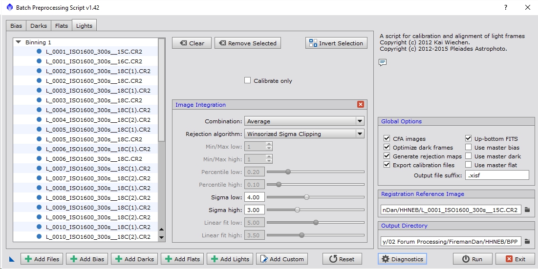
To begin, bring up PixInsight and go to the SCRIPT menu and pull down to Batch Processing then select BatchPreprocessing. This should bring up the Batch Preprocessing (BPP) script and should look like Figure 1 below.
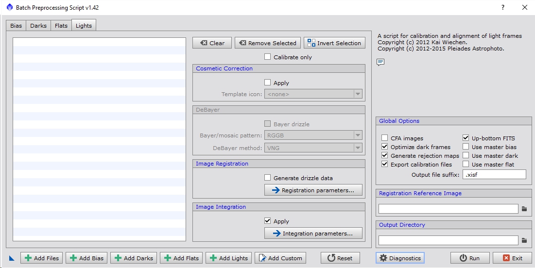
Figure 1: Batch Preprocessing form
There’s a lot going on here, so let’s break it down. First, you’ll notice for tabs at the top: Bias, Darks, Flats & Lights. These allow you to alter the various parameters associated with each of those image types. You need to understand what calibration are to really understand what the parameters mean. Unfortunately, that’s a bit much to cover in this one article. I’ll see about writing another one covering that. In the meantime there are many resources available describing calibration
Global Settings
There are also some global options on the right including a reference image for registration and the directory where all the output files will be stored. These effect all images involved.
The ‘Registration Reference Image’ is fairly straight forward to understand. During the BPP run the images will be aligned based on the star positions in each image. These may will likely from one frame to the next, sometimes intentionally (called dithering) and sometimes not (through polar mis-alignment, tracking/guiding errors or differential flexure). One file must be specified as the reference and all other images will be modified to match so that the stars in each of those frames line up with it. This process is called registration.
The ‘Output Directory’ just specifies where all the intermediate and master images will be stored. You’ll get a structure that looks like Figure 2 if you are using a DSLR or one-shot color (OSC) camera. If you have a monochrome camera and filters you will have additional folders for each of the filters you used in your data set. Your image acquisition software needs to be able to properly annotate the FITs headers so that BPP can understand what filters were used, however I think most of them do these days.
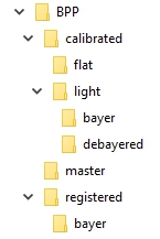
Figure 2: BPP Directory Structure for CFA Cameras
In this case BPP was the Output Directory I specified. There should be 3 folders under there: calibrated, master and registered. The bayer folders will only show up if you’ve turned on the drizzle options. The master folder is where you will find the final stacked images. There should be one for each data type you’ve entered (i.e. flats, darks, bias & lights).
Under ‘Global Options’ you have these items:
- CFA images: if you have a DSLR or OSC camera there is a color filter array (CFA) layered over the pixels in the sensor. Some pixels will get green , others will get blue and the rest red. This is very effective for DSLRs or planetary cameras where they are designed for a single exposure is lasting under a second. In that exposure red, green and blue data is all captured simultaneously this so there is no blurring of color information over time. Since most of deep space objects (DSOs) are static, at least in terms of our exposure times and achievable resolution, this isn’t really necessary, however those types of cameras can still be very effective for DSO imaging.
- Optimize dark frames: turning this on enables dark scaling. This mode takes the master dark and with the use of the master bias scales it so that it can be used to calibrate light frames of different exposure length and temperature. For those with DSLRs and non-temperature regulated OSC cameras this is very handy, making it so that you don’t have to build enormous libraries of darks at all sorts of temperatures and exposure times. The one downside is that it is not 100% accurate leaving you with some hot/cold pixels and potentially glow artifacts after calibration. In general it does a good enough job that the stacking/rejection (called integration) process can catch the remaining issues.
- Generate rejection maps: this is very useful as it will show you what pixels were rejected during integration. You can look to see if too many/few were rejected and also identify the intersection of all your light frames are (good for cropping your final stacked image). I always leave this option on.
- Export calibration files: actually, I’m not entirely sure what this option does. I’ve always left it on.
- Up-bottom FITS: This just changes the direction which FITs data is read. It should be set to match whatever you’ve set your FITS format to (which can be altered through the Format Explorer->FITS->Edit Preferences->Coordinate Origin). If you haven’t altered that setting then leave this option on as that is the PixInsight default.
- Use master *: if you already have an existing master bias, dark or flat you can check the appropriate box. I generally re-create master dark and bias frames every 3 months so I would turn those options on and when loading bias and dark frames I would only load those instead of all the sub frames to create them. It saves on processing time.
- Output file suffix: this identifies the format that the data will be saved in. As far as I know you can use .jpg if you just wanted, but don’t 😉 XISF (eXtensible Image Serialization Format) is the new default file format for PixInsight. You can change it to .fit or if you want your data to be more compatible with other image programs you could even use .tif. I just leave this as .xisf since I can always reformat an image to whatever I want later on.
Before we move on to the Lights tab we should talk about the icons and buttons on the bottom of the form (looking back to Figure 1). First, is the ‘New Instance’ icon at the lower left (it looks like a blue triangle). This allows you to drag an icon to the desktop with whatever settings and files you’ve specified so that it can be re-run with the exact same setup if desired. This can come in handy when testing things out. Moving towards the right there are 6 ‘add’ buttons. These allow you to load in the files you want to use to calibrate, register and integrate your data. If your acquisition software outputs FITs files and properly annotates the headers you should be able to use the ‘Add Files’ button and just select all of your images and the will be auto populated into dark, bias, flat and light categories. I haven’t had the best success with this option so in general I just use the individual ‘Add Bias’, ‘Add Darks’, ‘Add Flats’ and ‘Add Lights’ buttons to directly specify which files fall into a given category. It’s not going to hurt to try the ‘Add Files’ button and see if your data is loaded into the correct buckets. The ‘Add Custom’ button allows you to add in files and override data, like image type, filter, binning and exposure time (see Figure 3).
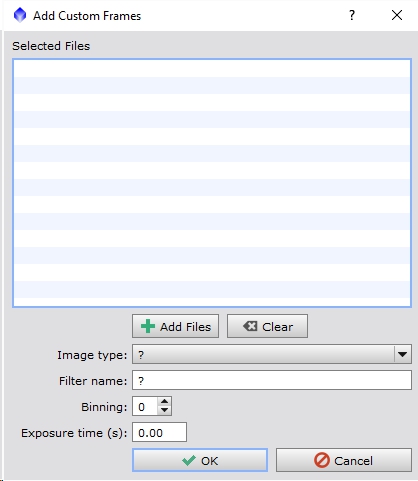
Figure 3: Adding Custom Images
The nest button is ‘Reset’ and is used to reset all the settings back to the defaults or to the settings from the last time you ran BPP. There’s a lot of settings so this can be useful to just level set things. It does not clear out the images already loaded in the current session. The ‘Diagnostics’ will do a check to see if you have everything loaded correctly. It will pop up warnings if, for example, you didn’t load your dark frames. The ‘Run’ button does exactly what you think, it runs the script and does all the calibration, registration and integration of your data. The ‘Exit’ but and the ‘X’ button in the upper right of the form do the exact same thing and exit out of BPP.
Bias Frame Settings
Now that we’ve covered the global settings, let’s look at the Bias tab and it’s associated settings as seen in Figure 4.

Figure 4: Bias Settings
You can see that by clicking on the Bias tab the settings change from the Lights and other tabs. There is no registration, almost no calibration and a few integration settings. This is because a bias frame is an attempt to capture what the fixed pattern noise looks like when reading the sensor. It accounts for several things that, if not calibrated out of your lights, will reinforce during the stacking process and show prominently in your final master light frame.
There are two types of overscan when referring to CCD and CMOS sensors. The first is the voltage offset in the sensor itself and is sometimes called the overscan level. The second type of overscan deals with pixels beyond the active imaging region. BPP is referring to the second type. Have you ever seen specs for a camera that show total pixels and active pixels? The total pixel count of the sensor will be higher than the active because there are physically more pixels on the chip. However, not all of them are ‘good’ and the manufacturers limit the access to the edges a bit to improve the yield of the sensors during the fabrication and testing process. In addition some of these pixels may be used for calibration purposes by the hardware and will never contain any real light data. It’s rare to find a camera where those pixels are not excluded during the read-out process, but there are some out there. I haven’t used one myself so I don’t feel qualified to describe how to use this section of the form.
Let’s go over the Image Integration settings for the bias frames:
- Combination: this specified the type of stacking method used. For bias frames this should always be ‘Average’ which simply means that all frames will be averaged together. The point of this is to remove the random noise so that the fixed pattern in the read-out signal can be removed from the light frame data.
- Rejection Algorithm: this is the algorithm used to determine what pixels within the stack are outliers. For example, the only outliers you should get from bias or dark frames is from sporadic events like cosmic ray strikes. Which algorithm you use is generally determined by the number of frames you have. A very exhaustive description of what each algorithm does can be found in the ImageIntegration process documentation both in PixInsight and on their website. In general terms I use Linear Fit Clipping if I have over 25 frames, Winsorized Sigma Clipping if I have between 15 and 25 frames, Averaged Sigma Clipping if I have between 9 and 15 frames, Percentile Clipping if I have between 5 and 9 frames and for frame counts below that I use Min/Max (you cannot have fewer than 3 frames in a stack).
- Min/Max low and high: if using the Min/Max algorithm I will generally specify 0 for the low and 1 for the high. This means the brightest pixel in every stack will be excluded. Transient events like cosmic rays should be caught reasonably well by this method even with very few frames. The disadvantage is that there is a high signal to noise ratio (SNR) penalty as you may be dropping 1/5th to 1/3rd of your data.
- Percentile low and high: this does a percent difference from the median of the stack to determine if a pixel is an outlier. Lower values will reject more pixels. I typically find the values of 0.2 and 0.1 to be a bit too aggressive. I usually use 0.4 and 0.3.
- Sigma low and high: sigma represents the standard deviation of a set of values, in this case the values in each output pixel stack. Standard deviation is very sensitive to outliers and is the basis for a lot of probability theory. It requires enough samples to generate a reasonable sigma value though and some of the variations on standard deviation, like Winsorized Sigma require even more. For darks and flats I find the sigma values of 4 and 3 to be far too low and typically set these way up to 6 and 5, although this will depend on you data set.
- Linear fit low and high: these values are also sigma like. At the heart of the linear fit algorithm is a standard deviation however I tend to set these values a little higher than I would the standard sigma. Something on the order of 7 and 6 is more typical of what I use for dark and bias frames.
With all of these methods some data is rejected (excluded from the average calculation) and higher values reject fewer pixels except for Min/Max. If the data is truly spurious then it would throw the average off so those events should be rejected. Ideally these values should be set so that only the data from those events is identified and excluded. Examining the rejection maps can help show you if this is the case with your current settings. For example, if you look at your master dark rejection maps (which should be displayed when you load the master dark if you have the ‘Generate rejection maps’ option on) and see a fairly even distribution of noise then your settings are probably to strong. If on the other hand you see almost no pixels then your settings are too week. If you see some short lines and curves in the rejection maps and not much else then you are correctly detecting and excluding the sporadic events like cosmic ray strikes.
Dark Frame Settings
Next is dark frame settings as seen in Figure 5.
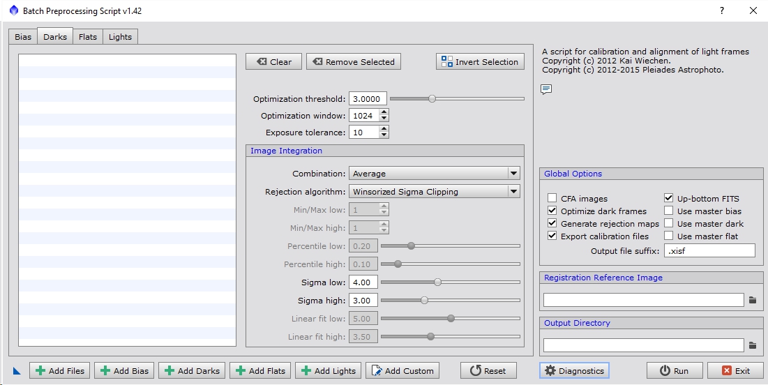
The Image Integration settings are identical to the bias frames settings and in general the settings you use will be very similar. The only difference is that most of us tend to take many more bias than dark frames so you may end up using Winsorized Sigma Clipping instead of Linear Fit Clipping, etc.
Above Image Integration there are three settings. The first two are related to dark optimization, which is not run when creating the master dark but instead are run inline when calibrating the light frame.
- Optimization threshold: this looks for outliers relative to the image itself, rather than relative to a stack and uses only those to determine how the dark should be scale if the ‘Optimize dark frames’ option is enabled. Essentially it is looking for the hot/cold pixels in the dark and then adjusting the scale factor based on how well it corrects those corresponding pixels in the light frame.
- Optimization window: this limits the area of the image used to do the dark optimization which speeds up the calculation. I’ve found it to be plenty fast with the default setting of 1024 and have left it alone. If you see errors about dark scale factors not being computed you may need to up this value or potentially use darks that are a little closer to the exposure time and temperature of your lights.
- Exposure tolerance: this just groups darks in buckets based on their exposure time. If your dark exposures are all within 10 seconds they will all get lumped into the same stack. Generally all my dark exposures are the same length so I don’t bother with this setting at all.
For the most part, I have rarely modified these 3 settings and they have worked quite well for 90% of the data I’ve thrown at BPP.
Flat Frame Settings
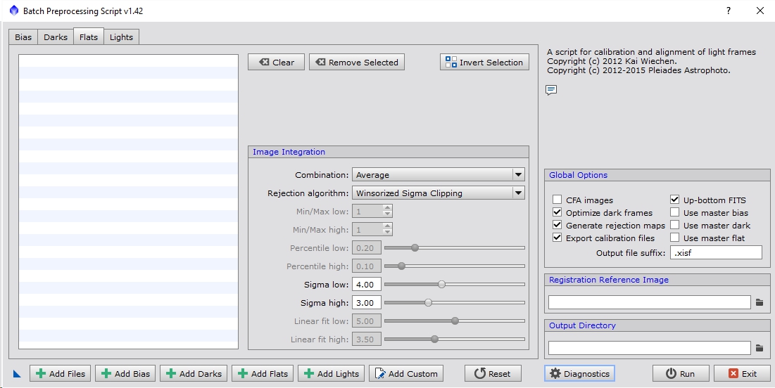
Figure 6: Flats Settings
Figure 6 shows the settings for flat frames. Once again we find the same Image Integration settings as we saw in the bias and darks tabs. Here the percentile/sigma/linear fit values typically need be a bit lower to accurately catch outliers. The default values of 4 and 3 work fairly well for a lot of data sets. You should still examine the rejection maps of the master flat (or flats if you have multiple filters) and see if they are correctly identifying sporadic events or too many or too few pixels. Sometimes it is difficult to catch only the sporadic events and in order to get them removed some percentage of other pixels have to be rejected. Just keep in mind that any rejected pixels reduces the total SNR of the stack so you want to keep the number of rejected pixels as low as possible while still rejecting the random events.
Light Frame Settings
Figure 7: Lights Settings
Figure 7 is a duplicate of Figure 1, shown here so it is closer to the text. The first thing I’ll mention is, you get the same selection manipulation icons (clear, remove, invert) as you do with the other image types for modifying your list of light files.
The next option moving down is ‘Calibrate only’. If you turn this on you will see the Image Registration and Image Integration section grey out. This option disables those two features so that BPP only creates the master bias, dark and flat then calibrates the lights with those images. It does not register or stack the lights into a final image. Since most of the individuals using BPP are doing so because they are just learning or trying to get a quick idea of what their data looks like when stacked this option will most likely be left disabled. With it disabled you will get a master light frame for every filter type in your data set.
Cosmetic Correction is a process that removes hot, cold and stuck pixels. This overlaps some with darks which also remove hot/cold pixels, however darks are not 100% accurate, especially when using optimization. Some sensors also have extremely low dark noise so you can opt to not use darks at all and just rely on cosmetic correction and rejection during stacking to ignore those pixels. To use Cosmetic Correction you need to have loaded up the process before starting BPP, adjusted the settings how you like and then saved it to the desktop by dragging its ‘New Instance’ icon to the PI desktop. Then when you start BPP you can turn on the ‘Apply’ option under Cosmetic Correction and select that Template icon. I’m not going to discuss the Cosmetic Correction tool here and will instead direct you to my manual integration tutorial if you want to use it. For those just starting out, I wouldn’t use this to start anyway and those that are just trying to get a quick spin of their data probably aren’t too concerned about a few defective pixels showing up so for the purposes of this tutorial I will suggest leaving it disabled.
The Debayer options may be grey-ed out if the ‘CFA images’ options is disabled in the ‘Global Options’. As stated previously if you are using a DSLR or OSC camera you need to turn that option on. Under Debayer there are 3 options:
- Bayer drizzle: this option turns on drizzling. This is a way to theoretically increase the resolution of the final stacked image, both in terms of total pixel count as well as true measurable resolution (i.e. smaller angular measurements of the stars). If you have a lot of light frames (at least 25 but ideally more) and your image scale is very large, and you have a reasonably powerful computer I would recommend turning this on. Keep in mind that if you have a 12 mega pixel image then your output image will actually be closer to 48 mega pixels (BPP does a 2×2 scale when drizzling). Drizzling trades SNR for resolution so expect the image to look noisier if you use this, which is why I recommend having a lot of data if you want to try it. In order for this option to be enabled to the corresponding drizzle option under the ‘Image Registration’ section must also be on.
- Bayer/mosaic pattern: this is the patter of how the color filter array is layered over the pixels of the sensor. All Canon cameras I’ve come across use RGGB. For DSLR, if you don’t know what your pattern is, try loading a raw image into PI and monitor the console window. It should identify the bayer pattern based on information in the raw header. For OSC camera owners you should be able to ask the manufacturer what your pattern is. If you can’t find it or get a response from them you can take some daylight images that have known colors in them and try different patterns until you find the one that gives you the correct colored output image. I wouldn’t do this from within BPP but instead use the Debayer process.
- DeBayer method: this option determines how the colors will be interpolated so that you get red, green and blue information at each pixel, rather than a pixel containing just red information for example (which is the case if you have a CFA camera). The VNG and Bilinear options maintain the resolution of the sensor, so if you have a 12MP camera the output image will stay 12MP. The Superpixel method takes a group of 4 pixels and treats them as one, effectively cutting the resolution in quarter. If you have a very small image scale, for example if you have a long focal length instrument paired with a small pixel camera then you might consider using the Superpixel method, otherwise I would use VNG.
The next option is ‘Image Registration’. As noted above in the DeBayer section the ‘Generate drizzle data’ option must be on if you want to drizzle your data and increase the resolution of your output image. If you are just beginning with PixInsight I would leave the drizzle options off for now. If you click on the ‘Registration parameters…’ button it will change the tab to look like Figure 8, exposing the registration settings. Click on the red ‘x’ icon to go back to the previous settings.
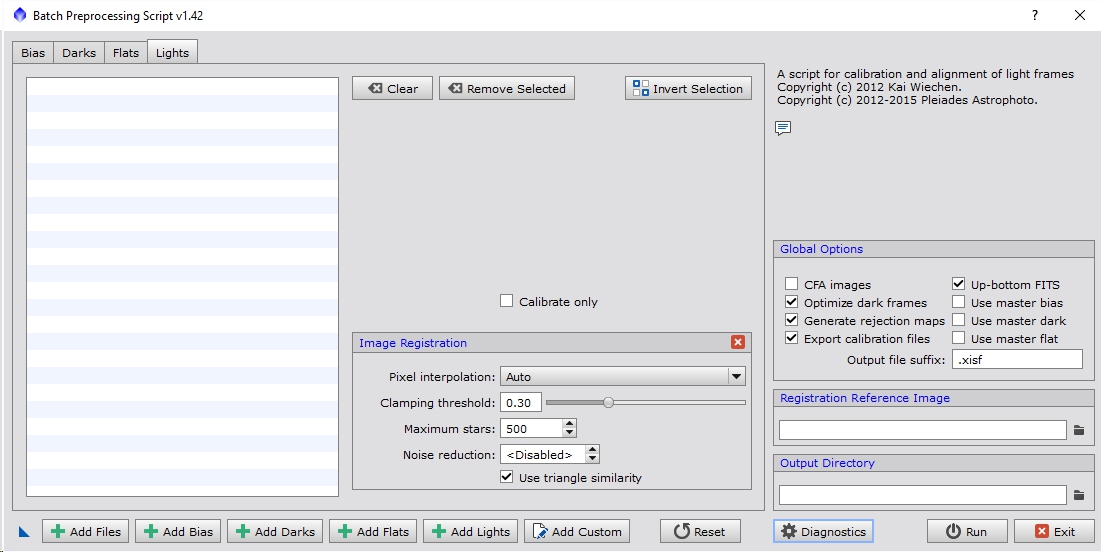
Figure 8: Registration Settings
The same ‘Calibrate only’ option is here, just shifted down some. If you are looking at these parameters you want that option disabled. There are 5 registration options, which I generally leave alone. Here is what they mean and do:
- Pixel interpolation: this determines how the data will be sampled when translating it during registration. The default of ‘Auto’ works well in most cases. Some options will produce more blurred results or sharper results with with ringing artifacts. In general interpolation is not your friend and always destroys some information in your data, however it is a necessary evil in most circumstances. The exception being if you are using the drizzling option. While the data is interpolated as part of registration drizzle runs an extra step that goes back to the original un-registered data and uses a totally different method of sampling. It is more immune to ringing artifacts and maintains the noise profile in your images. Like stated above it should only be used in specific circumstances though.
- Clamping threshold: this adjusts how ringing around high contrast pixels is handled. It is only available for some of the interpolation options. In general I leave this at 0.3.
- Maximum stars: this limits how many stars will be used as part of the registration process. Using smaller values will improve run time but may decrease the accuracy of the registered images effectively blurring the output. If you have a fast computer, you may consider pushing that value up but in general I would leave it alone.
- Noise reduction: this option will blur (well, it’s not exactly a blur) the image a bit to remove some of the high frequency noise making it easier to identify stars. I typically run with a value of 1. Higher values remove consecutively lower frequencies of noise. A value of 1 means that noise on the scale of 2 pixels will be removed and a value of 2 will reduce noise of around 4 pixels, etc. If you have a very large image scale, such that fainter stars show up as single pixels then you would want this disabled.
- Use triangle similarity: this is one of the methods PixInsight uses to match patterns of stars. The default PI behavior is to use Pentagons which is more computationally expensive. It’s very rare when triangle similarity does not work so I typically leave this enabled.
Registration is where some of the first limitations of BPP start to show. If you have a very large or very small image scale there’s no way to control how PI detects stars. Frequently if you have registration issues you have to run BPP in ‘Calibrate only’ mode and then run the StarAlignment and ImageIntegration processes separately to stack the calibrated light frame data.
Next we have ‘Image Integration options. It isn’t actually recommended that you use the built in light frame integration (in fact you’ll get a warning about it), however for a quick spin of your data or for someone just learning the results should be fine. The check box for ‘Apply’ allows you to disable/enable it. If you click on the ‘Integration parameters…’ button it will alter the tab to look like Figure 9.
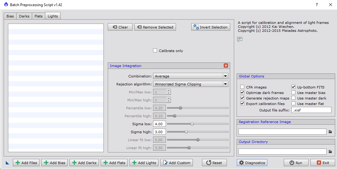
Figure 9: Integration Settings
These settings are identical to the ones seen in the Bias, Darks and Flats settings. For the most part, I generally use similar settings to the flat frames depending of course on the number of frames that I have. The default settings are a good place to start. That being said, the reason why it isn’t recommended that you use the integration from within BPP is because it’s results are rarely optimal for any given data set. Being able to tweak all the settings of the full ImageIntegration process can typically result in a higher quality result. As I said before, if you are just starting out with PI or just looking for a quick spin of your data using the built in Image Integration is fine.
For a functional example of using BPP please see my: A Simple Process tutorial.
Hello Dave,
First, thank you for putting in all the effort to document the various techniques and flow use with PI. A few times lately, I have experienced BPP not flattening properly with either raw, or master flats. A few years ago I ran into an issue with BPP not recognizing flats for certain filters that was due to FITs header name difference. At that time, BPP would put up a warning. Now, no warning, just poorly or unflattened frames. It seems this started after the major PI update recently? Have you heard of this happening. I’ve posted questions on PI user forum and got a couple responses which either I was already doing or did not help.
thanks in advance for any ideas you may have
Hi Steve,
I don’t have any ideas off-hand. Normally I don’t use BPP at all and use a full manual flow, however if you can post something like 5 frames for each frame type (flats, darks, bias, lights, maybe a couple filters worth) I can take a look and see if I can debug it.
Just in terms of general debug, there are several reasons why the flat correction may be bad.
1) Darks or bias were not used or did not match in terms of exposure length, temperature, ISO, etc.
2) The flats were not taken at the same ISO, temperature, etc.
3) The flat from a different filter was applied to the light
4) Something changed in the optical system between when the flats and lights were taken
5) Nearby light sources cause internal reflections that aren’t present in the flats or lights
Given what you said, I would suspect 1, 2 or 3. Have you noticed anything in the console saying a dark wasn’t applied or anything like that?
Regards,
David
Hi David,
Thanks for responding. I should have added, the exact set of master dark & bias and flats were used to manually calibrate the same light frames and they came out just fine. That’s why I’m puzzled what’s going on. I’m 100% sure the flats used were taken at the end of the night the light frames were captured on. So the last few targets, I’ve had to manually calibrate. In the past, BPP has worked very well.
It definitely sounds like something got mismatched, like it didn’t find a dark that matched a light, the dark scaling was significantly off or it used the wrong dark/bias to calibrate the flats or lights. I know they have some code to try to auto detect what matches what but something may have happened with either the FITs headers or the BPP code that has thrown that off.
Regards,
David
Thanks again,
Dark scaling not used. Master dark is the same duration and temp as the lights. My best guess is BPP script is mis-interpreting what goes with what based on FITs header info. On the bright side, I’m getting more experience with manually calibrating which is cool. Maybe an updated SGP version changed the way headers are written (another wild guess).
It certainly doesn’t sound like there is anything wrong with what you are feeding BPP, so likely it is a mismatch somewhere. I’ve found I get better results going through the manual process anyway, which is one of the reasons I don’t feel compelled to use BPP anyway. I’m glad the manual process is working for you though. I’m sure digging through the logs might help identify where it is going wrong. There is a ton of information it spits out as it runs the various processes under the covers. Honestly, I’ve never found the manual process much more time consuming and it is easier to debug as you go along.
Regards,
David
Did you make a script for fixing the SBIG pedestal ?
Can you send me a copy?
Max
Hi Max,
I’m not certain which script you are referring too. I have worked with some people who have had pedestal issues before but generally everything I have done was through PixelMath and not in the form of a script.
Regards,
David